How-To / / 3D Printing Topography
A newly updated plugin for Grasshopper allows users to create high resolution 3D topography of anywhere in the world, based off the most recent NASA scan data. Some regions of the world have higher resolution scans than others, but the NASA data is still the most accurate available for just about anywhere.
In this how-to blog post, Fathom Industrial Designer Ava DeCapri walks through the steps to create a 3D printed topographic map (please note, this tutorial is for experienced-to-advanced users).
- Identify the area you’d like to print.
- Figure out the latitude and longitude coordinates for the bounding box of that area. You can use this NASA website to find exact longitude and latitude. Note: This can involve a very heavy data set that Grasshopper and Rhino will have a hard time processing. With a smaller area, Rhino and Grasshopper will be able to process faster.
- Download the Grasshopper Plugin for Rhino online at Rhino website and download the Elk Plugin for Grasshopper.
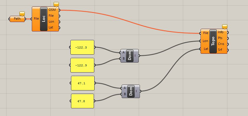
- Open the Elk plugin and pull out the location component.
- Download the .IMG for the area that you need. The National Map provides a good option for this step.
- Create a file path component and drop in the .IMG file you downloaded by right-clicking the component and selecting “Set One File Path.”
- Drag and drop the location component from Elk onto the canvas. Connect the file path component to the file on the location component from Elk. This may take a while if your area is large.
- Drag and drop the topography component onto the canvas. This component is asking you to supply three sets of data, the file from the location component, which you already have and the latitude and longitude. To supply the latitude and longitude you determined in the beginning of the process, you need to create a custom domain.
- Create two “custom domain” components and two panels for each domain. Write the upper and lower limits of the bounding box you determined in the beginning of the process as latitude and longitude into the two panels. Plug each of those into the custom domain components (A and B) to create a range of latitude and longitude. Plug those custom domains into the latitude and longitude, respectively.
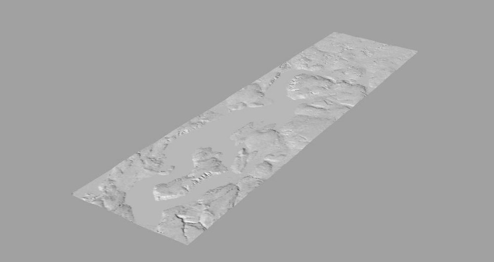
- You will see the surface now in Rhino, but it is just a preview. Hover over the surface output on the topography component and right-click to select “Bake.” You now have a zero thickness surface that is the high resolution topography of a given area.
- Create desired thickness for the topography using the Rhino thicken command or you can do the same in Magics.
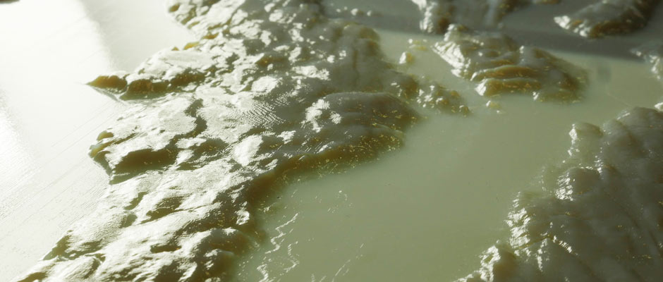
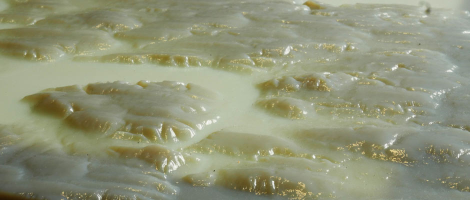
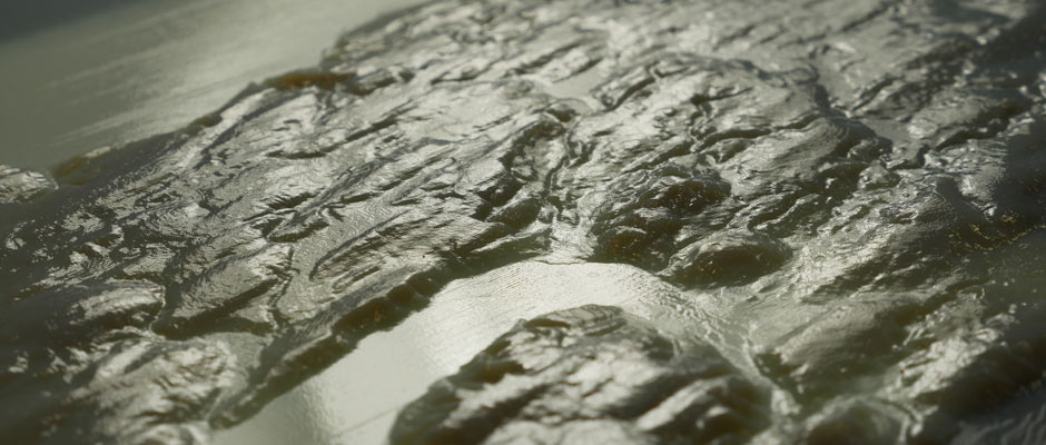
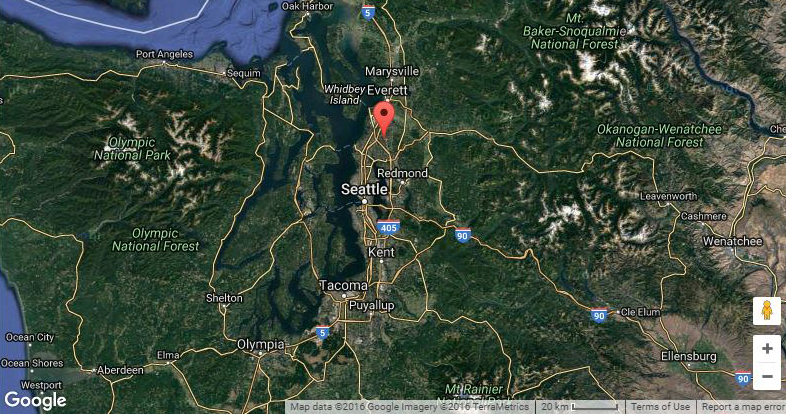
- 3D print away! The close-up images below are of high-resolution PolyJet prints (by Fathom) of the Seattle metropolitan region, 3D printed in VeroGray material at 32 micron layer height.
