Changing the Way Products are Designed, Prototyped & Manufactured
Being on the forefront of testing emerging additive technologies for prototyping and production applications is part of Fathom’s mission to change the way products are designed, prototyped and manufactured—in this featured Q&A, Applications Engineering Manager Tony Slavik and his team explore the practical use of its in-house Studio System by Desktop Metal, a lower barrier-of-entry solution for metal-based 3D printing.
////// FROM 3D SCANNING TO THE RUMBLE OF AN ENGINE
To further assess the capabilities of the Studio System, the Fathom applications engineering team took a stock engine component, 3D scanned it, refined the CAD file, additively built it, post-machined key features and successfully installed it in the engine of a Fathomers Volkswagen van. The point of the test was to thoroughly examine the technology—running feasibility and validation tests of additive technologies to determine practicality is a key focus for this Fathom team. Watch the video to learn more then check out the Q&A below.
Why did you choose this stock component for testing the Desktop Metal technology? What was the objective?
The Fathom application engineering team chose this component because it is relatively recognizable, relatable and realistic. This component is typically casted and requires multiple manufacturing post-operations such as CNC machining and welding. The objective was to test the accuracy and function of Desktop Metal’s Bound Metal Deposition (BMD) process in a real-world application. Our goal was to explore an additive alternative for prototyping metal parts (quantities of 10 or less).
Another application being evaluated by the Fathom team is how to use this technology for manufacturing fixtures because the BMD process allows users to create a sparse internal structure within larger solid areas. As a result, this ability can be useful for making lighter-weight, high-strength metal parts without employing more advanced lattice tools such as nTopology or 3-Matic (not every application warrants the cost or it’s considered overkill for simple designs).
Can you walk us through each step, from beginning to end?
We first acquired a standard rocker arm since it is a part that we could easily reverse engineer. Next, the shape was 3D scanned using our in-house FARO laser scanner.
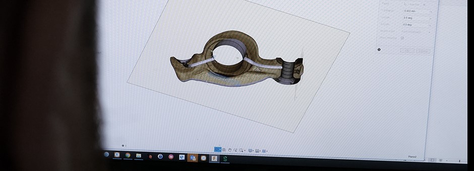
From there, we took the point cloud data that was generated and created a watertight mesh. Using Fusion360, a great tool for working with solid models and meshes, we were then able to model critical features to lay over the scanned data (e.g. creating an internal channel as pictured below). After that, all digital layers were merged and converted it to a single STL file.
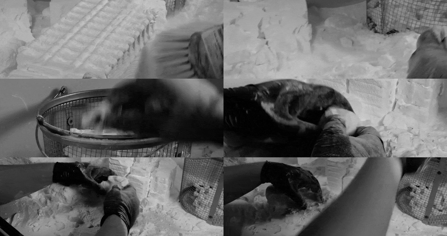
The fabrication phase came next. We additively built the final STL file in 17-4 PH stainless steel using a Desktop Metal Studio 3D printer. This was a straightforward process once we figured out the support parameters needed. After 3D printing the part, the rocker arm went through a debinding and sintering process.
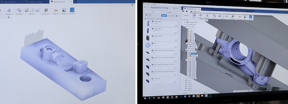
We took the shape of the rocker arm and subtracted it from a soft jaw blank shape and 3D printed the fixture in VeroWhite on a PolyJet-based system while waiting for the previous process to complete. This was an important step because choosing to do so made the machining process much simpler. Due to the organic/complex surfaces, it would have been difficult to CNC machine the fixture.
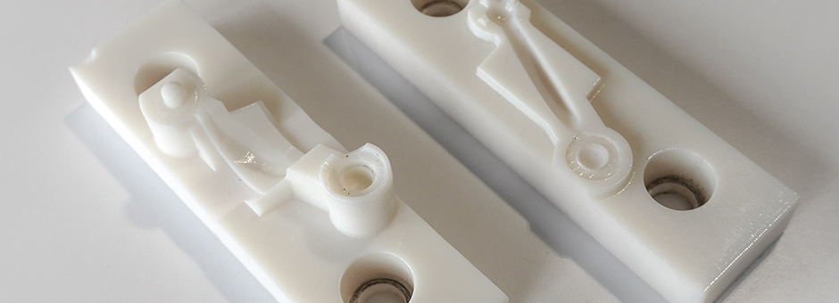
With the soft jaw ready to go, we machined the center hole of the rocker arm to achieve a smooth surface. We also tapped the threaded hole on the end of the arm.
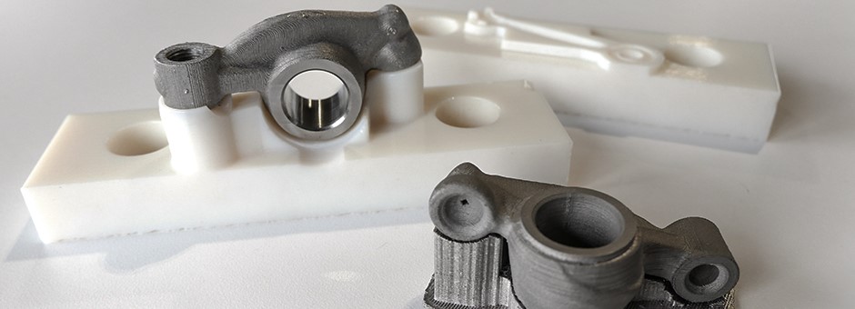
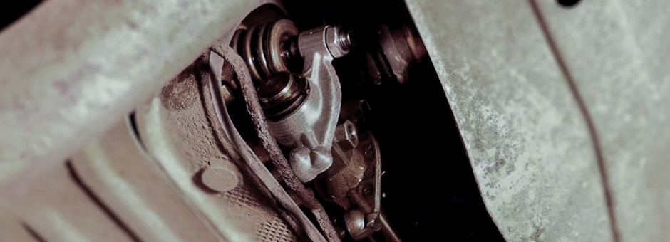
Finally, the rocker arm was cleaned thoroughly and successfully installed in the 4-cylinder engine of a Fathomer’s 1987 Volkswagen Vanagon.
What was challenging about this application example?
-
Accuracy was a challenge at first, but we trialed different orientations and support styles for the Desktop Metal 3D printer to achieve the desired result
-
The internal channel was also a challenge—we would not have been able to remove support material from the inside, so it was modeled in a diamond shape (a continuous self-supporting angle)
-
Lastly, support was not filling below some of the features—since we wanted to maintain as much accuracy as possible, we lowered the self-supporting angle to ensure a support structure was built under the entire model
What’s your overall perspective on metal-based additive technologies today?
Metal-based additive technologies have steadily gained acceptance as a manufacturing process across industries throughout the last few decades, especially in the automotive and aerospace industries. Because of the specialized nature of the parts being produced, processes and technologies have evolved to meet specific needs and applications. However, as these technologies and processes have become more refined, efficient and cost-effective, the opportunity to use metal-based additive technologies is ever-increasing.
Understanding the difference between each type of metal-based additive technology (e.g. Laser Powder Bed Fusion, Direct Energy Deposition, and Electron Beam Powder Bed Fusion) and the applications they are best suited for, is critical to further growing the adoption of Direct Digital Manufacturing (DDM).
For more information on the topic, the Fathom team recently worked with Design World to author an 8-page editorial on how to get the most out of additive manufacturing and it includes a section on metal-based additive technologies.


